16
Solar
Thermal
Projects
Note to Reader: This chapter is
directly excerpted from ‘Solar Energy System and Design’ by W.B. Stine and R.W.
Harrigan, published by John Wiley 1985.
It represents the state-of-the-art of solar thermal projects at the end
of the 1970’s and has not been revised.
Almost 25 percent of the energy resources used by the
There are a number of projects in
operation today that collect solar energy as heat and then apply this heat to
industrial processes or convert it to electrical energy. Most of these were
initiated by and received total support from the
16.1
Industrial Demands
Process steam is used as a source of heat for many
industrial processes. Saturated steam is
used because it provides large amounts of heat at a constant temperature (the
saturation temperature). The temperature-pressure relationship for saturated
steam is shown in Figure 16.1. This
shows, for example, that if an industrial plant had a 1.0 MPa (130 psig) steam
line, the steam would have a temperature of 180ºC (356ºF).
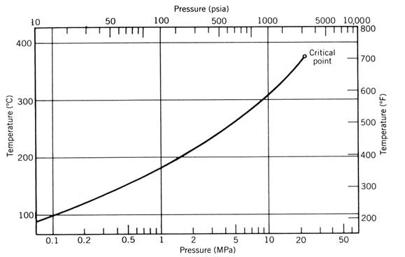
Figure 16.1 Temperature
of saturated steam. Most industrial
process steam is saturated and meets these conditions.
Industry requires
process heat over a wide temperature range.
The distribution of the temperature at which this heat is used is shown
in Figure 16.2. Also shown in this
figure is a second distribution that includes the amount of energy required to
preheat the steam from ambient temperature.
It can be seen that one-half of the thermal energy needed by industry
could be supplied by systems providing heat at temperatures less than 250ºC
(482ºF). In addition to process steam, some industrial operations use process
hot water (e.g., for sterilizing and degreasing) and hot air (e.g., for drying
products).

Figure 16.2 Temperature
requirements of industrial process heat.
The lower curve is the temperature at which heat is supplied. The upper curve includes the energy required
for preheating from ambient temperature (anonymous, 1977).
Some industrial installations
have found it economically feasible to produce electrical energy on size and
use the “waste” heat rejected by this process, to provide low-grade process
heat for the purposes discussed above.
This concept called “total energy” or “cogeneration” is especially
relevant to industrial processes where the demand for significant amounts of
electrical energy and low-grade thermal energy are used in close
proximity. The solar total energy system
at
16.2 Survey of Solar Thermal Systems
16.2.1 Process Heat Systems
Many industrial processes requiring thermal energy
have been studied for their potential as economic
applications of solar thermal energy systems. Many of these design studies have
come to fruition in the form of operational solar energy systems, and these are
summarized in Table 16.1. The low-temperature applications (temperature
below 100ºC) are mostly industrial drying operations, a number of which are
associated with agriculture.
Table 16.1.
Systems Providing Industrial Process Heat


Most of the collectors
used in the low-temperature applications are fixed-aperture, non-concentrating
(i.e., flat-plate) collectors. Exceptions
include Gilroy Foods, which uses evacuated-tube collectors with slight
concentration, and the La Cour Kiln project, which includes a north-facing flat
reflecting surface for irradiance enhancement.
Other exceptions include York Building Products, where the SLATS
concentrating collector (discussed in Chapter 9) and the Campbell Soup system,
where flat-plate collectors are used as preheaters for parabolic trough
concentrators.
Water is the collector heat-transfer
fluid for most of the low-temperature systems. For applications where the
demand is for hot air, two systems use air as the collector heat-transfer
fluid, and the other two use water in the collector field, thereby requiring
the use of a heat exchanger to produce the hot air for the demand.
Thermal storage is provided in many
of the low-temperature systems to meet the mismatch between insolation
availability and the demand. Usually this is in the form of an insulated
hot-water storage tank; however, in the Lamanuzzi and Pantaleo project, heat is
stored in a large bin of riverbed granite pebbles.
The mid-temperature
projects listed here range in demand temperatures from 113ºC (235ºF) process
hot water (pressurized) for tractor parts degreasing to 215ºC/2.17-MPa
(419ºF/300-psig) process steam, which heats oil for potato frying. All the collectors used in this group are
concentrating collectors with single-axis tracking apertures. The singular application of a point focus
concentrator for process heat is in the Capitol Concrete Project. This is not
the usual dish-type concentrator, but a group of curved reflecting slats that
reflect light into a cavity receiver.
For these
mid-temperature systems, the collector fluid chosen has been either pressurized
water or a heat-transfer oil. Since the collector fluid should not boil in
order to provide maximum heat transfer, systems employing water are pressurized
above the saturation pressure of water at the collector's operating temperature
(see Figure 16.1). For example, the
Ore-Ida collector field is maintained at a pressure of 4.25 MPa (600 psig) in order
to prevent boiling at its nominal operating temperature of 247ºC (477ºF). Systems using heat-transfer oils may be
operated at a low pressure because of the low vapor pressure of the oils
selected.
Systems using oil as the
heat-transfer fluid are typically installed on the ground. One advantage of using water as the collector
heat-transfer fluid is that the system can be installed on a rooftop without
posing a fire hazard. This capability is taken advantage of by three of the mid-temperature
systems. Although none of the low-temperature systems use a flammable
heat-transfer fluid, some chose to place the collectors on the ground for
economic reasons.
Few of the mid-temperature process heat systems
include a means of storing the collected thermal energy other than small
“buffer storages” required for smooth system control during short-term
transients. The one exception is the Johnson & Johnson system, where a
large flash steam tank provides some energy storage. Details of the design and operating
characteristics of these systems may be found in reports by Harley and Stine
(1983) and (1984).
16.2.2 Solar Thermal Power Systems
A number of systems have been built that convert
solar energy collected as heat into mechanical or electrical energy. These use some type of thermodynamic power
conversion cycle. Early interest in
these systems was for agricultural irrigation; however, more recent systems
include an industrial total energy system and systems that generate only
electricity. Table 16.2 summarizes the basic design features of these solar
thermal power systems.
Table 16.2. Solar
Thermal Power Systems

Rankine cycles using organic working
fluids were chosen for the early projects using parabolic trough concentrators.
This was due to the small size of the cycle and low operating temperatures.
More recent systems have capitalized on the known technology of steam Rankine
cycles.
Because of the increase of power
conversion cycle efficiency with heat-supply temperature, solar collection
concepts that operate efficiently at high temperatures such as parabolic dishes
and central receivers, are considered as prime candidates for use in future
solar thermal power systems. This will happen if their overall cost per unit of
electricity output can be made competitive with lower temperature, less
efficient, but less costly schemes. One project outside the
16.2
Description
of Representative Systems
Four of the systems
listed in Tables 16.1 and 16.2 have been selected for an in-depth description
since their designs represent typical design for that type of system. These include the following:
·
Johnson & Johnson –
a typical
industrial process heat application using parabolic troughs.
·
Coolidge Irrigation
Project – electrical power production using a medium-temperature parabolic
trough field.
·
Shenandoah Solar Total
Energy Project – a total energy system using medium-temperature parabolic dishes.
·
Solar One – electrical power
production using a high-temperature central receiver system.
16.2.1 Johnson & Johnson Solar Process
Heat System
The Johnson &
Johnson plant located in
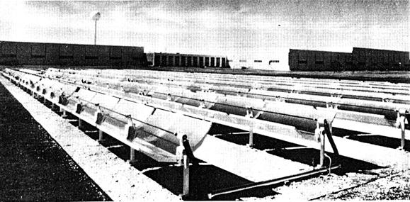
Figure 16.3 The
Johnson & Johnson solar energy
system at
Collector Field: The collector field consists of 1070 m2
(11,520 ft2) of parabolic trough collectors using water as a
heat-transfer fluid. The tracking axis
orientation is northeast – southwest and was chosen because of the orientation
of the existing plant facility.
The basic collector module is 1.83 m
(6 ft) ´ 3.05 m (10 ft), and one drive string consists of eight
modules. There are six drive strings connected in series to form one fluid
delta-T string with the total field
consisting of four delta-T strings
connected in parallel. Water is pumped through these fluid loops at a pressure
of 2.14 MPa (310 psia) at a constant flow rate of 14,000 kg/h (31,000 1b/h).
Figure 16.4 shows the layout of the collector field.
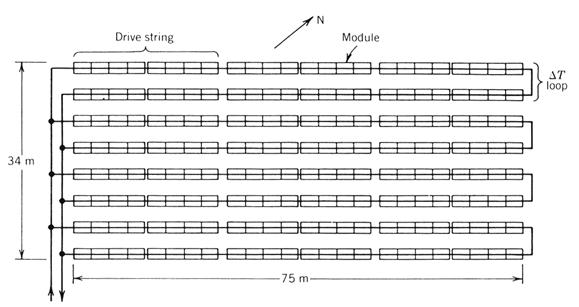
Figure 16.4 Collector
field layout for the Johnson & Johnson solar system showing the fluid
piping.
System: Pressurized water from
the collector field is pumped through a throttling valve, reducing its pressure
slightly, and then into the flash boiler-storage tank. Water is pumped from the bottom of this tank
back to the collector field, where it receives additional heating. No attempt is made to optimize thermal stratification
in the flash boiler – storage tank.
When process steam is
required, the pressure of the flash boiler is reduced slightly to the
saturation pressure of the water in storage.
The water in the tank then boils and is passed through a throttle valve
into the plant steam lines at 175ºC/0.86 MPa (345ºF/125 psia). The overall system is depicted schematically
in Figure 16.5.
Energy Flows: The thermodynamic properties of the water at different
points in the system are shown in Table 16.3 (storage tank is charged to 50 percent
of its capacity). The stations at which
the properties are described are noted in Figure 16.5.

Figure 16.5 Flow
diagram for the Johnson & Johnson solar process steam system.
The
thermodynamic processes that take place are shown in Figure 16.6 on
temperature-entropy coordinates. There
are two basic processes associated with this system. Process 1-2-3-4 is the heating of the water
in storage by the solar loop, which occurs during the daytime as long as the
sun is shining. The second process,
process 1-5, is the flash evaporation process which lasts only a short period
of time and occurs nominally four times a day.
The flow of energy for these processes is depicted graphically in Figure
16.7.

Figure 16.6 Processes
of the Johnson & Johnson solar process heat system (not to scale).

Figure 16.7 Energy
flow diagram for the Johnson
& Johnson solar energy system.
Specifications: Table 16.4 presents
detailed specifications for this system.
Table 16.4. Specifications of the Johnson & Johnson
Solar Energy
Process Heat System
System:
Operator
– Johnson & Johnson, Southwestern Surgical Dressing Plant
Location
–
Demand
– process heat used in gauze bleaching process
Process steam 174ºC/ 0.86 MPa (345ºF/ 125 psia)
Flow rate – intermittent with maximum of 726 kg/h (1600 lb/h)
Daily energy use – 9.5 GJ (9 ´ 106 Btu)
Collector Modules:
Type
– parabolic trough with glass-covered tubular receiver
Manufacturer
– Acurex Corp., Model 3001
Aperture
– 1.83 m ´3.05 m (6 ft ´ 10 ft)
Reflective
surface – Coilzak polished aluminum
Concentration
ratio – 36
Collector Field:
Number
of modules – 192
Total
aperture area – 1070 m2 (11,517 ft2)
Orientation
– northeast/southwest
Modules
on single-tracking drive – 8
Land
use – 40% (4.6-m row spacing)
Collector Field Fluid Flow:
Heat-transfer
fluid – pressurized water 2.5 M Pa (360 psia)
Delta-T string – 32 modules in series
Number
of delta-T strings – 4
Flow
control – constant flow rate
Maximum
field outlet temperature – 215ºC (419ºF)
Storage:
Type
– flash boiler/pressurized water
Medium
– pressurized water
Volume
– 19 m3 (5000 gal)
Thermal
capacity – 29.3 GJ (27.8 ´ 106 Btu)
Maximum
temperature – 215ºC (419ºF)
Minimum
temperature – 174ºC (345ºF)
Operating time at maximum demand – 5.46 h
16.2.2 Coolidge Solar Irrigation Facility
The system shown in Figure 16.8 is located on the
Dalton Cole farm south of
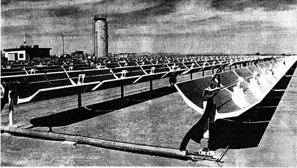
Figure 16.8 The Coolidge solar irrigation facility in Coolidge,
AZ. Courtesy of Sandia National Laboratories.
Collector Field: The collector field consists of 2140 m2
(23,035 ft2) of parabolic trough
collectors with their tracking axis oriented in the north–south direction. This orientation was chosen to maximize the
solar power generating capability in the summer, when the greatest demand for
irrigation water exists. The layout of
the collector field is shown in Figure 16.9.

Figure 16.9 Collector
field layout of the Coolidge solar irrigation facility showing the fluid
piping.
As in the Johnson & Johnson
system, there are eight 1.83-m (6-ft)-wide ´ 3.05-m (10-ft)-long collector
modules connected to a single-tracking motor to form a drive string. Six of these are connected in series to form
a delta-T string. The total field consists of eight delta-T strings.
The heat-transfer fluid used in this
application is a low-vapor-pressure oil, Caloria HT-43, a petroleum distillate
marketed by Exxon Corporation. The flow
rate of this fluid is varied so that the field outlet temperature remains at a
constant 288ºC (550ºF).
System: The system consists of three heat-transfer loops as shown in
Figure 16.10.
The first loop takes cooled Caloria HT-43 from the bottom of the storage
tank and passes it through the collector field and returns it to the top of the
storage tank. The second, also a HT-43
loop, takes hot oil from the top of the storage tank, circulates it through a
vaporizer heat exchanger, and returns it to the bottom of the storage tank or
back to the collector field directly.
The third loop circulates liquid
toluene through the vaporizer heat exchanger, where it is vaporized and slightly
superheated to 268ºC/1.03 MPa (515ºF/150 psia).
The toluene then expands through a single-stage impulse turbine. After leaving the turbine, the low-pressure
toluene is passed through a regenerator heat exchanger before being condensed
into liquid in the vapor condenser. A pump
raises the pressure of the liquid toluene before it gains heat in the regenerator
and then passes into the vaporizer. The
vapor condenser is cooled by water spray over the condensing coils and a fan
that provides airflow through the unit.
In the photograph of the system
(Figure 16.8), the storage tank is the tall cylindrical tank. The power conversion system is located to the
left of that.
Energy Flows. A simplified full power case described below shows the
energy flows to and from the system. The major simplifying assumptions are that
the pipe pressure and heat losses are negligible and that the solar input
provides just enough energy for full power operation.
The thermodynamic state properties
of the toluene in the power conversion cycle are given in Table 16.5. The stations at which these properties are
given are shown on Figure 16.10.
Table 16.5 Operating Fluid Properties for the Coolidge
(AZ)
Solar Irrigation Facility
|
|
Pressure |
Temperature |
Enthalpy |
Mass Flow |
|
Station |
(MPa) |
(ºC) |
(kJ/kg) |
(kg/h) |
|
1 |
0.0118 |
45.6 |
-739.6 |
6545 |
|
2 |
1.05 |
47 |
-737.2 |
6545 |
|
3 |
1.05 |
142.8 |
545.4 |
6545 |
|
4 |
1.05 |
267.2 |
33.01 |
6545 |
|
5 |
0.0118 |
183.3 |
107.1 |
6545 |
|
6 |
0.0118 |
59.4 |
300.6 |
6545 |
|
A |
|
200 |
420 |
15.388 |
|
B |
|
288 |
652 |
15.388 |

Figure 16.10 Flow diagram
for the Coolidge solar irrigation system.
Figure 16.11 shows these states on
temperature–entropy coordinates. The
cycle diagram is superimposed on the saturation curve for toluene. Toluene is called a "drying fluid"
because the amount of superheat increases as pressure is reduced at constant
entropy. Because of this characteristic, it is important to include a regenerator in the cycle. The regenerator
transfers heat from the hot vapor leaving the turbine, thereby cooling it until
it approaches the temperature of the condenser.
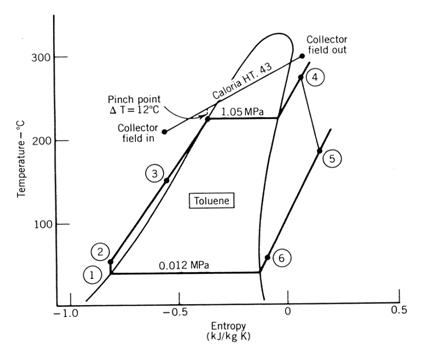
Figure 16.11 Processes of
the Coolidge solar irrigation system (not to scale).
For a solar input of 970 W/m2
normal to the collector aperture, the flow of energy through the system is
shown in Figure 16.12. The condition shown is for no energy going into or from
the storage. One point to note here is the high gearbox-generator loss of 40 kW
or 16.4 percent of the mechanical power generated by the cycle. This is due to
the small size of the cycle and the use of a single-stage impulse turbine. The
turbine operates at 9300 rpm and a gearbox must be used to reduce the speed to
1800 rpm to match the speed requirements of the electrical generator.
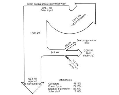
Figure 16.12 Energy flow
diagram for the Coolidge solar irrigation system. Operation is at full power with no storage
interaction.
Specifications: The system design specifications of this system are
presented in Table 16.6.
Table 16.6. Specifications of the Coolidge (AZ)
Solar Irrigation Facility
System:
Operator
– DOE / Arizona Public Service Co.
Location
–
Demand
– electrical power for remote site deep-well agricultural irrigation
Output
– 150 kW electricity maximum
Collector Modules:
Type
– parabolic trough with glass-covered tubular receiver
Manufacturer
– Acurex Corp., Model 3001
Aperture
– 1.83 m ´ 3.05 m (6 ft ´ 10 ft)
Reflective
surface – FEK 244 (3M Corp)
Concentration
ratio – 36
Collector Field:
Number
of modules – 384
Total
aperture area – 2140 m2 (23,035 ft2)
Orientation
– north/south
Modules
on single-tracking drive – 8
Land
use – 30% (6.5-m row spacing)
Collector Field Fluid Flow:
Heat-transfer
fluid – Caloria HT-43 (Exxon Corp.)
Delta-
T string – 48 modules in series
Number
of delta-T strings – 8
Flow
control – constant outlet temperature
Field
outlet temperature – 288ºC (550ºF)
Field
return temperature – 200ºC (392ºF)
Storage:
Type
– thermocline tank
Medium
– Caloria HT-43 oil
Volume
– 114 m3 (30,000 gal)
Thermal
capacity – 19.8 GJ (18.7 ´ 106 Btu)
Maximum
temperature – 288ºC (550ºF)
Minimum
temperature – 200ºC (392ºF)
Operating
time at maximum demand – 6 h
Power Conversion Cycle:
Type
– Rankine cycle with superheat and regeneration
Working
fluid – toluene
Turbine
inlet – 268ºC/1.03 MPa (515ºF/150 psia)
Condenser – 40.5ºC/ 10 kPa (105ºF/1.46 psia)
Thermal
efficiency – 20%
16.2.3 Shenandoah Solar Total Energy Project
This system located in

Figure 16.13 The
Shenandoah solar total energy project at
Collector Field: The collector field consists of 114 7-meter-diameter
parabolic dishes with cavity receivers.
The total aperture area is 4352 m2 (46,845 ft2). The dishes track about their polar and
declination axes, and each dish has its own tracking motors and focal feedback
system, receiving input from a central control system. Figure 16.14 shows a layout of this field.
All collectors are connected in
parallel to the supply and return heat-transfer fluid lines. The heat-transfer
fluid chosen for this application is Syltherm 800, a silicon-based fluid, is
manufactured by Dow-Corning Corporation.
The fluid can withstand the 399ºC (750ºF) maximum operating temperature
of the system. The flow rate to the
field is varied and balanced so that the outlet temperature of each collector
is 390ºC (734ºF).
System Description: The system is comprised of two basic
flow loops; the solar field heat-transfer loop and the water-steam loop of the
energy conversion cycle. It is shown
schematically in Figure 16.15. Valves
and a few minor connections have been omitted for clarity. The solar field loop contains Syltherm 800,
which, after being heated in the solar field, is
passed through the steam generator heat exchangers (actually three units – one
for preheat, one for boiling, and one for superheat). In this loop is also included a small 41.6 m3
(11,000 gal) hot oil storage tank sized to provide for continuous operation
during short-term insolation transients. Also included is an auxiliary heater
that may be used in series with the collector field to maintain a constant
temperature for operating the steam turbine.

Figure 16.14 Collector
field layout of the Shenandoah solar total energy project showing the fluid
piping.

Figure 16.15 Flow
diagram for the Shenandoah solar total energy project.
The water–steam loop produces
electricity using a Rankine cycle with single point extraction. Steam leaves the turbine at a higher than
usual temperature in order to supply heat to a lithium bromide absorption
chiller. Steam not required by the chiller is passed through a condenser that
rejects cycle heat to the surroundings.
Some of the steam flow is extracted
between the high- and low-pressure turbines. Part of this steam is used to
preheat the boiler feedwater in a deaerator–feedwater heater. The other portion of the extraction steam
goes into a de-superheater, where it is mixed with condensate in order to bring
the steam to saturated vapor before being passed into the process steam supply
line.
The absorption chiller receives heat
from the turbine exhaust steam and rejects heat to the surroundings by a
cooling tower. In the chiller, heat is
extracted at a temperature of 7.2ºC (45ºF) from a chilled water system going to
the knitwear factory.
Energy Flows: The thermodynamic states of the water-steam
system at various points in the Rankine cycle for a full-demand example are
shown graphically in Figure 16.16 and given in Table 16.7. For this example it was assumed that pressure
or heat loss in the interconnecting piping was negligible.

Figure 16.16 Processes of
the Shenandoah solar total energy project (not to scale) for the full-load example.
Table 16.7. Operating Fluid
Properties for the Shenandoah (GA) Solar
Total Energy System
|
|
Pressure |
Temperature |
Enthalpy |
Mass F low |
|
Station |
(MPa) |
(ºC) |
(kJ/kg) |
(kg/h) |
|
1 |
0.145 |
110.3 |
462.4 |
3451 |
|
2 |
0.862 |
110.5 |
462.7 |
3451 |
|
3 |
0.862 |
168.4 |
705.1 |
3835 |
|
4 |
4.93 |
169.5 |
709.6 |
3835 |
|
5 |
4.93 |
382.2 |
3151.3 |
3835 |
|
6 |
0.862 |
225.1 |
2886.0 |
979 |
|
7 |
0.145 |
115.6 |
2697.7 |
2855 |
|
8 |
0.1 45 |
115.6 |
2697.7 |
1767 |
|
9 |
0.145 |
110.3 |
462.0 |
30.4 |
|
10 |
0.862 |
225.0 |
2886.0 |
384 |
|
11 |
0.862 |
225.0 |
2886.0 |
596 |
|
12 |
0.862 |
173.5 |
2768.1 |
626 |
|
l3 |
0.145 |
1 I0.3 |
462.0 |
626 |
|
21 |
0.145 |
115.6 |
2697.7 |
1088 |
|
22 |
0.145 |
110.3 |
462.0 |
1088 |
|
23 |
7.2 |
30.4 |
72,837 |
|
|
24 |
12.8 |
53.6 |
72,837 |
|
|
25 |
35.0 |
146.4 |
117,647 |
|
|
26 |
29.4 |
123.2 |
117,647 |
|
|
A |
260 |
460.1 |
32,234 |
|
|
B |
399 |
750.6 |
32,234 |
|
Also shown in Figure 16.16 are the
temperatures of the Syltherm 800 heat-transfer fluid as it passes through the
steam generator heat exchangers. Note
that the pinch point temperature difference is 22.2ºC (40ºF).
The energy flows into
and out of the system for an insolation level of 778 W/m2 are shown
in Figure 16.17. The operating condition
for these flows is the full-demand condition shown in the temperature-entropy
diagram, where the electrical, process steam and chiller demands are a
maximum. Although thermal-to-electric
conversion efficiency is only 12 percent, the conversion efficiency from solar
to all forms of useful energy is 44 percent.
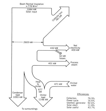
Figure 16.17 Energy flow
diagram for the Shenandoah solar total energy project for the full-load
example.
Specifications: The specifications of this system are presented in Table 16.8.
Table 16.8.
Specification Summary of the Shenandoah (GA) Solar
Total Energy System
System:
Operator
– Georgia Power Company
Location
–
Demand – electrical power, process steam, and
chilled water for space cooling for knitwear manufacturing operations
Output
– 400 kW electricity maximum, 626 kg/h (1380 lb/h) process steam at 0.86 M Pa/
173ºC (125 psia/344ºF), 468 kW (133 tons) of cooling
Collector Modules:
Type
– parabolic dish with cavity receiver
Manufacturer
– General Electric/Solar Kinetics Inc.
Aperture
– 7 m (23 ft) diameter
Reflective
surface – FEK 244 (3M Corp.)
Concentration
Ratio – 234
Collector Field:
Number
of modules – 114
Total
aperture area – 4352 m2 (46,845 ft2)
Orientation
– two-axis tracking
Each
module has own tracking drives
Land
use – 41%
Collector Field Fluid Flow:
Heat-transfer
fluid – Syltherm 800 (Dow-Corning)
All
modules connected in parallel
Flow
control – constant outlet temperature
Field
outlet temperature – 399ºC (750ºF)
Field
return temperature – 260ºC (500ºF)
Storage:
Type
– small buffer tank
Storage
medium – Syltherm 800
Volume
– 41.6 m3 (11,000 gal)
Thermal
capacity – l.33 GJ (1.26 ´ 106 Btu)
Maximum
temperature – 399ºC (750ºF)
Minimum
temperature – 363ºC (685ºF)
Operating
time at maximum demand – 1 hr
Power Conversion Cycle:
Type
– Rankine cycle with superheat
Working
fluid – water
Turbine
inlet – 382ºC/4.93 MPa (720ºF / 715 psia)
Condenser – 110ºC/145 kPa (231ºF/21 psia)
Thermal
efficiency – 18%
Turbine
extraction port used for process steam
Chiller:
Type
– lithium bromide absorption chiller
Heat
in – 102ºC (215ºF)
Heat
rejection – 29ºC (85ºF)
Chilled
water – 7.2ºC (45ºF)
16.2.4 Solar One Central Receiver Pilot
Plant
Solar One is the first large-scale application of the
central receiver concept. It is located just outside

Figure 16.18 The Solar One
10-MW central receiver pilot plant at
Heliostat Field: The heliostat field consists of 1818 heliostats,
each with a slightly concave reflective surface area of 39.9 m2 (430
ft2). Of these, 1240 are
located north of the receiver tower and 578 south of the tower as shown on
Figure 16.19.

Figure 16.19 Heliostat field layout of the Solar One 10-MW central
receiver pilot plant.
A single heliostat consists of 12
slightly concaved mirror panels fabricated by bonding a second surface glass
mirror to a honeycomb core that, in turn, is bonded and sealed to a steel
enclosure pan. The panels are aligned so
that each segment reflects the sun’s image on the receiver. Each heliostat is individually tracked about
the azimuth and elevation axes by two 1/8-kW (1/6-hp) motors.
Storage: Thermal storage is provided for approximately 4 hours of
operation at reduced power levels. The storage consists of a mixture of crushed
rock, sand, and Caloria HT-43 heat-transfer oil (a product of Exxon). The maximum storage temperature of 304ºC
(580ºF) is limited by oil decomposition.
Therefore, the steam
leaving the receiver must be cooled before charging the storage to its maximum
temperature. Likewise, the conversion
cycle must operate at reduced output during operation on steam generated by the
stored heat.
System Description: The Rankine cycle power conversion
system is shown schematically in Figure 16.20. There are three flow loops shown
that comprise the three primary operating modes:
power production from solar-generated steam, power production from
storage-generated steam, and storage charging.

Figure 16.20 Simplified flow schematic for the Solar One 10-MW
central receiver pilot plant.
To produce power from the
high-temperature solar-generated steam, feedwater is pumped from the condenser
through a number of feedwater heaters and then out to the receiver tower and up
to the receiver. Here the water is
heated by the sun’s radiation reflected onto the receiver surface. Superheated
steam leaves the receiver at 516ºC/10.85 MPa (960ºF/1573 psia) and, after being
piped down the tower, enters the turbine.
Some steam is bled at four extraction ports and used to heat the
receiver feedwater. Most of the steam
leaves the last stage of the turbine and is condensed at 43ºC (109ºF) in the
condenser, which is cooled by a wet cooling tower.
When more steam is available from
the receiver then is needed for power production, the excess is passed through
a de-superheater to reduce its temperature to the maximum storage
temperature. The steam is then passed
through a heat exchanger, where it heats the cool Caloria HT-43 storage oil,
which is pumped from the bottom of the storage tank.
The heated oil is returned to the top of the storage
tank, where it transfers heat to the rock and sand. The cooled steam is then returned to the
power cycle at heater #2, where it provides feedwater heating.
When the receiver can no longer produce
high-temperature, high-pressure steam, preheated feedwater leaving the
deaerator is diverted to the storage.
Here a heat exchanger transfers heat from the hot oil at the top of the
storage to the feedwater, producing 274ºC/2.65-MPa (525ºF/385-psia) steam.
The cooled oil is returned to the
bottom of the storage tank, and the steam enters the turbine at an admission
port placed a few stages downstream from the entry port for the high-pressure
receiver stream. The remainder of the
flow path is similar to that used when operating on steam generated at the
receiver.
Energy Flows: The thermodynamic states
of the steam and oil for two operating conditions are shown graphically in
Figure 16.21 and given in Table 16.9. The first condition is for full power
production from solar-heated steam excess steam charging the storage. The second condition is for power production
from storage-generated steam. These data
include the pressure and heat from the interconnecting piping.
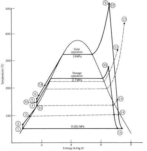
Figure 16.21 Processes of the Solar One 10-MW central receiver
pilot plant (not to scale) (both solar steam
generation and storage generation of steam are shown).
Table 16.9. Operating
Fluid Properties for Solar One Operating from Solar-
Generated Steam and Storage-Generated Steam
|
|
Pressure |
Temperature |
Enthalpy |
Mass Flow |
|
Station |
(MPa) |
(ºC) |
(kJ/kg)
|
(kg/h) |
|
Full-
Power Solar Operation with Storage Charging |
||||
|
1 |
0.0085 |
42.8 |
178.3 |
43,500 |
|
2 |
0.965 |
42.8 |
179.2 |
43,500 |
|
3 |
0.945 |
92.2 |
388.1 |
43,500 |
|
4 |
0.283 |
131.7 |
553.1 |
61,200 |
|
5 |
14.09 |
l34.4 |
574.0 |
61,200 |
|
6 |
14.05 |
167.8 |
7 I 5.8 |
61,200 |
|
7 |
14.00 |
204.4 |
876.2 |
61,200 |
|
8 |
13.15 |
204.4 |
876.2 |
59,400 |
|
9 |
10.85 |
515.6 |
3404.7 |
59,400 |
|
10 |
10.10 |
510.0 |
3395.4 |
52,000 |
|
11a
|
1.87 |
333.9 |
3079.9 |
4,130 |
|
12a |
0.834 |
437.8 |
3344.2 |
2,590 |
|
l3 |
0.283 |
151.1 |
2760.9 |
1,860 |
|
14 |
0.0862 |
97.8 |
2591.2 |
1,497 |
|
15 |
0.0085 |
42.8 |
2324.0 |
38,800 |
|
21 |
10.10 |
510.0 |
3395.3 |
7,260 |
|
22 |
10.10 |
343.3 |
2888.7 |
9,070 |
|
23 |
9.64 |
223.9 |
962. 1 |
9,070 |
|
24 |
l.138 |
181.7 |
769.2 |
8,210 |
|
25 |
1.034 |
181.7 |
2777.2 |
862 |
|
26 |
0.283 |
160.0 |
2777.2 |
862 |
|
A |
0.496 |
218.3 |
074.2 |
77,600 |
|
B |
0.186 |
304.4 |
1636.8 |
77,600 |
|
Operation
from Storage Generated Steam |
||||
|
1 |
0.0085 |
42.8 |
178.3 |
46,200 |
|
2 |
0.965 |
42.8 |
179. 2 |
46,200 |
|
3 |
0.945 |
91.7 |
385.8 |
46,200 |
|
31 |
0.281 |
131.1 |
550. 8 |
49,900 |
|
32 |
3.38 |
132.2 |
555.4 |
49,900 |
|
33 |
2.65 |
273.9 |
2935.2 |
49,900 |
|
13 |
0.281 |
133.9 |
2619.1 |
3,720 |
|
14 |
0.0855 |
97.2 |
2468.1 |
4,200 |
|
15 |
0.0085 |
42.8 |
2228.7 |
41,300 |
|
C |
0.496 |
301.7 |
1617.2 |
539,000 |
|
D |
0. 186 |
221.1 |
1090.9 |
539,000 |
The storage charging process and the
storage discharge process are shown on Figure 16.22 a and b. Starting at station 21, the steam is first de-superheated
and then passed through the oil-steam heat exchanger to heat the storage
oil. After leaving this heat exchanger,
the condensate is throttled into a flash tank, where the steam produced is used
to preheat receiver feedwater in the deaerator and the liquid goes to feedwater
heater #2.
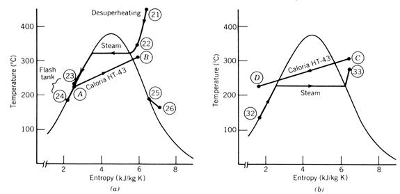
Figure 16.22 Thermodynamic
process diagrams for storage charging and discharging of the Solar One 10-MW
central receiver pilot plant.
The storage discharge is shown in
Figure 16.22b, where the heat
transfer oil is used to generate steam.
Here again the pinch point limits the oil discharge temperature and thus
the amount of heat which can be extracted from storage.
Figure 16.23 shows the energy flows
for full power output with excess energy available for storage. The maximum solar input case shown here is
for noontime at the summer solstice.

Figure 16.23 Energy flow
diagram for summer solstice noontime operation for the Solar One 10-MW central
receiver pilot plant.
Specifications: The specifications for this system are presented in
Table 16.10.
Table 16.10.
Specifications of the Solar One Central Receiver Pilot Power Plant
System:
Operator
–
Location
–
Demand
– electrical power for utility grid
Output
– 10 MW electricity maximum
Heliostat Modules:
Type
– heliostats with external receiver on top of tower
Manufacturer – heliostats, Martin Marietta; receiver,
Rocketdyne; system, McDonnell Douglas
Aperture
– 6.9 m ´ 6.9 m (22.6 ft ´ 22.6 ft)
Reflective
surface – silvered glass (second surface)
Reflective
surface area – 39.9 m2 (430 ft2)
Concentration
ratio – 282
Heliostat Field:
Number
of heliostats – 1818
Total
aperture area – 72,540 m2 (237,990 ft2)
Orientation
– north and south of tower
Each
module has own tracking drive
Land
use – 25%
Receiver:
Tower height – 91 m (298
ft) (including receiver)
Receiver size – 7 m (23
ft) diameter/ 13.7 m (45 ft) high
Heat-transfer fluid –
water/steam at 10.6 MPa (1537 psia)
Flow–6 south-facing panels are preheaters in series with the
remaining 18 steam-generating panels (one panel forms 4% of circumference)
Flow control – constant
outlet temperature
Steam outlet temperature
– 516ºC (960ºF)
Return temperature – 203ºC
(397ºF)
Storage:
Type
– thermocline rock–oil
Medium
– 1-in. crushed granite, sand, and Caloria HT 43 oil
Rock
– 4.11 ´ 106 kg (4532 tons)
Sand
– 2.06 ´ 106 kg (2266 tons)
Oil
– 907 m3 (239,600 gal)
Volume
– 4228 m3 (149,300 ft3)
Thermal
capacity – 522 GJ (495 ´ 106 Btu)
Maximum
temperature – 304ºC (579ºF)
Maximum
temperature – 223ºC (435ºF)
Operating
time (at 7 MW) – 4h
Power Conversion Cycle–Receiver Steam Operation:
Type
– Rankine cycle with superheat
Working
fluid – steam
Turbine
inlet – 510ºC/10.1 MPa (950ºF/1465 psia)
Condenser – 43ºC/8.4 kPa (109ºF/ 1.24 psia)
Thermal
efficiency – 35%
Power Conversion Cycle – Storage Steam Operation:
Type
– Rankine cycle with superheat
Working
fluid – steam
1urbine
inlet – 274ºC/2.65 kPa (525ºF/385 psia)
Condenser – 43ºC/8.4 kPa (109ºF/l.24 psia)
Thermal efficiency – 25%
References
Anonymous (1977), “Analysis of the Economic Potential of Solar Thermal Energy to Provide
Industrial Process Heat,” Intertechnology Corporation Report C00/2829/76/I,
February.
Harley, E. I.,
and W. B. Stine (1983), “Solar Industrial Process Heat (IPH) Project Technical Report; October 1981-September
1982,” Sandia National Laboratories Report SAND83-2074, October.
Harley,
Hunke, R. W., and J. A. Leonard (1983), “Solar Total Energy
Project Summary Description”, Sandia National Laboratories Report SAND82-2249,
March.
Larson, D.I. (1983), “Final Report of the Coolidge Solar
Irrigation Project,” Sandia National Laboratories
Report SAND83-7125, October.